
Manufacturing excellence begins with intelligent tooling design. Sheet metal stamping operations depend entirely on dies engineered with meticulous attention toward countless variables. A single die might produce millions of parts throughout its service life. Initial design decisions ripple through production for years afterward.
Understanding die design principles separates successful stamping operations from struggling ones. This comprehensive exploration examines every critical aspect that designers must consider when creating stamping tooling.
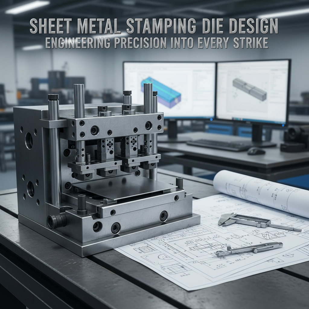
Fundamentals of Stamping Die Architecture
Stamping dies transform flat metal blanks into functional three-dimensional components through controlled plastic deformation. Dies consist of precision-machined components working together harmoniously. Upper die halves attach directly onto press rams. Lower die halves mount onto press beds or bolster plates.
When presses cycle, upper and lower die sections come together with tremendous force. Sheet metal trapped between these sections experiences shearing, bending, stretching or combinations of these deformation modes. Geometry emerges through carefully orchestrated material flow.
Die design complexity varies enormously across applications. Simple blanking dies merely cut flat shapes from coil stock. Progressive dies perform multiple operations sequentially as material advances through stations. Transfer dies move parts between independent stations mechanically. Compound dies complete multiple operations simultaneously during single press strokes.
Each configuration offers distinct advantages and limitations. Selection depends on production volume requirements, part complexity and economic considerations.
Essential Die Components Explained
Every stamping die comprises numerous precisely manufactured elements. Understanding component functions helps designers make informed decisions.
Die Blocks Provide Foundation
Lower die blocks typically consist of thick steel plates providing rigid mounting surfaces. Upper die shoes mirror this construction. These massive components resist deflection under stamping forces. Insufficient rigidity allows deflection and misalignment causing premature wear.
Die block material selection affects performance significantly. Cast iron offers excellent dimensional stability at moderate cost. Tool steel provides superior strength but increases expense. Some designs incorporate steel plates with cast iron backing for optimized economics.
Punch and Die Openings Create Geometry
Punches represent male tooling components that push material into cavities or through openings. Dies contain female openings receiving punches with carefully controlled clearances. Together these elements create part features.
Clearance between punch and die affects cut edge quality dramatically. Excessive clearance produces ragged edges with large burrs. Insufficient clearance causes excessive wear and galling. Optimal clearance depends on material thickness and properties specifically.
Typical clearances range from 5% up toward 10% of material thickness per side. Harder materials generally require larger clearances. Softer materials tolerate tighter clearances successfully.
Strippers Control Material Movement
Stripper plates prevent sheet metal from lifting with ascending punches after cutting operations. Spring pressure or hydraulic cushions hold material firmly against die surfaces. Without proper stripping action, parts stick onto punches creating havoc.
Fixed strippers remain stationary throughout press cycles. Spring-loaded strippers move with material initially before compressing during forming. Each style suits different applications optimally.
Pilots Ensure Accurate Registration
Progressive dies advance strip material incrementally between stations. Precision pilots entering previously punched holes guarantee accurate positioning. Without reliable piloting, features drift progressively out of tolerance.
Pilot design requires careful attention. Diameters must clear holes easily without excessive slop. Chamfered ends facilitate entry. Lengths provide sufficient guidance without binding.
Lifters Extract Parts Cleanly
After forming completion, parts must exit dies reliably. Knockout pins or spring-loaded lifters push finished components free from cavities. Inadequate knockout force leaves parts stuck requiring manual removal.
Lifter placement affects part flatness. Unbalanced lifting creates distortion. Designers distribute knockout points strategically around part perimeters.
Material Flow Considerations
Metal doesn’t simply conform magically into die cavities. Understanding material flow mechanics enables better die design fundamentally.
Drawing Operations Require Careful Planning
Deep drawn parts form through sequential stretching and compression. Material flows from flange areas toward cavity bottoms. Controlling this flow prevents tearing, wrinkling or uneven thickness distribution.
Draw ratios quantify severity. Deeper draws relative toward blank diameters create higher ratios. Exceeding material capabilities causes failure. Multiple progressive draws often become necessary for extreme geometries.
Blank holder pressure influences material flow dramatically. Excessive pressure restricts flow causing tearing. Insufficient pressure allows wrinkling. Adjustable cushions provide process flexibility.
Bend Relief Prevents Cracking
Sharp corners concentrate stresses severely. Bends terminating at edges often crack without proper relief features. Small notches or holes interrupt stress concentration patterns.
Relief sizing follows established guidelines. Depths typically equal material thickness minimally. Widths range from half thickness upward. Geometric specifics depend on material ductility.
Stretch Forming Demands Uniform Distribution
Complex contours often require significant stretching. Material must elongate uniformly without localized necking. Die surfaces should encourage gradual thickness reduction throughout forming zones.
Lubricants reduce friction allowing better flow distribution. Die polishing minimizes galling tendencies. Gradual contours prevent abrupt strain concentrations.
Clearance Calculations Matter Immensely
Proper clearances between mating die components determine cut quality and tool longevity fundamentally. Several factors influence optimal clearance selection.
Material thickness provides baseline reference. Soft materials like aluminum tolerate tighter clearances around 5% of thickness. Harder materials like stainless steel require 8% or more. Ultra-high-strength materials might need 10% clearance.
Cut edge quality requirements affect decisions too. Applications tolerating some edge raggedness allow larger clearances. Precision parts demanding clean edges need tighter control.
Punch and die wear patterns reveal whether clearances sit within acceptable ranges. Excessive wear on punch sides indicates insufficient clearance. Heavy burrs suggest excessive clearance. Monitoring wear helps optimize clearances empirically.
Die Material Selection Strategy
Tooling materials dramatically affect die performance and longevity. Careful selection balances cost against expected production volumes.
Tool Steels Dominate Production Dies
Oil-hardening tool steels like O1 provide excellent toughness at moderate cost. These grades suit prototype tooling and short production runs beautifully.
Air-hardening grades like A2 offer superior dimensional stability during heat treatment. Distortion becomes less problematic. Precision dies benefit from these characteristics.
High-speed steels like M2 deliver exceptional wear resistance. Long production runs justify added expense. Abrasive materials like silicon-containing steels demand hard tooling.
Carbide Inserts Extend Life Dramatically
Carbide possesses hardness far exceeding tool steel. Inserts installed at critical wear points multiply die longevity enormously. However carbide remains brittle and expensive.
Hybrid designs incorporate carbide punches within tool steel holders. This approach optimizes economics while maximizing wear resistance where needed most.
Coatings Enhance Surface Properties
Various coating technologies improve die performance without changing base materials. Titanium nitride coatings reduce friction and galling. Chromium nitride offers excellent corrosion resistance.
Physical vapor deposition methods produce thin, hard coatings adhering tenaciously. Coating selection depends on specific wear mechanisms encountered.
Progressive Die Design Principles
Progressive dies represent perhaps most sophisticated stamping tooling. Multiple stations perform sequential operations as strip material advances incrementally.
Station Planning Requires Strategic Thinking
Operation sequencing affects feasibility fundamentally. Designers must anticipate how earlier operations influence subsequent ones. Bends created at one station might interfere with punches at following stations.
Scrap skeleton must remain intact throughout progression. Premature separation causes misfeeding. Final station typically separates finished parts from carrier strips.
Pitch Distance Determines Efficiency
Distance between stations affects material utilization directly. Smaller pitch conserves material but complicates tooling. Larger pitch simplifies die construction but wastes metal.
Optimizing pitch balances these competing factors. Complex parts with tight tolerances often require larger pitch allowing robust construction.
Stock Guides Maintain Alignment
Material must advance accurately between press strokes. Channel-style guides constrain lateral movement. Adjustability compensates for material width variations.
Spring-loaded guide blocks accommodate minor thickness variations. Excessive clamping force marks material surfaces. Insufficient pressure allows wandering.
Transfer Die Advantages
Transfer systems mechanically move parts between independent die stations. Compared with progressive dies, transfer systems offer distinct benefits for certain applications.
Large parts exceed practical limits for progressive die construction. Transfer systems eliminate restrictions on part dimensions. Each station operates independently.
Complex forming operations sometimes require part rotation or flipping between stations. Transfer mechanisms accomplish this easily. Progressive dies cannot reorient parts fundamentally.
Transfer dies allow mixing different press types. Initial blanking might occur on mechanical presses while deep drawing uses hydraulic equipment. Optimization happens station-by-station.
Prototyping and Testing Strategies
Even expertly designed dies rarely perform perfectly initially. Systematic development processes refine designs toward production readiness.